
Shared-power DC charging
DC Flexible Charging Stack240–360 kW
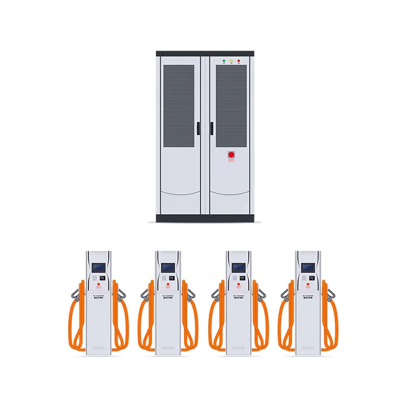
A central power system with separate dispensers. Plan the shared capacity, per-port limits and cable routes around the fleet’s arrival pattern and future bay layout.
View specifications- Equipment format
- Power cabinet + remote dispensers
- Selection focus
- Concurrency & dispenser layout
Application fit
Built into the right operating plan.
Fleet depots · Multi-bay charging hubs. Selection depends on the site’s electrical conditions and the actual vehicle-use pattern.
Share a defined power pool
Allocate the available system output across connected vehicles within the model’s control and per-port limits.
Separate power and parking
Place power cabinets and dispensers around access, cable routes and maintenance requirements.
Plan expansion honestly
Review spare electrical capacity and model-supported expansion before assuming more bays can be added.
Technical selection
Know what you are specifying.
These are configuration references. The current model datasheet and written scope determine the equipment supplied.
Swipe to view the full specification table →
| Parameter | Selection reference | Confirm for your project |
|---|---|---|
| Total system output | 240 / 320 / 360 kW references | Shared capacity, not an output promise for each dispenser. |
| Power architecture | Central cabinets with remote dispensers | Cabinet count and supported dispenser configuration are model-specific. |
| Per-port limit | Maximum power, voltage and current: confirm per model | A port may not accept the full system capacity; check dispenser, cable and vehicle limits. |
| Allocation logic | Supported sharing modes: confirm per configuration | Review minimum allocations, simultaneous-use behavior and control priorities. |
| Input service | Voltage, current and required capacity: per system design | Confirm transformer, feeder, protection and any staged expansion. |
| Cable routes | Cabinet-to-dispenser runs: per approved layout | Review manufacturer distance limits, conduit, civil works and maintenance access. |
| Metering & network | Model-specific management, OCPP and metering options | Confirm backend compatibility, billing and fleet scheduling interfaces. |
| Order evidence | Configuration-specific datasheets, drawings, safety documents and warranty | Review the complete cabinet-and-dispenser package, not only one component. |
Project inputs
Three checks before selection.
Use the project’s actual conditions to define a compatible configuration with your installer or engineer.
Peak concurrency
Fleet composition, shift arrivals, required energy and simultaneous charging demand.
Physical layout
Cabinet location, dispenser count, cable runs, vehicle movement and future bays.
Expansion plan
Spare connection capacity, supported modules and the triggers for electrical upgrades.
Quality & production evidence
Quality should be traceable.
Review the evidence for the proposed equipment, from assembly and routine testing to the documents supplied with the order.
Parameters that match
Confirm model identity, rated input/output, connector, enclosure, cable limits and protection against the current datasheet.
Factory & functional records
Agree which assembly, routine electrical, protection and functional test records are available for the selected model.
Documents that apply
Review applicable safety/listing evidence and backend compatibility for the exact hardware, firmware and destination.
A defined delivery package
Confirm serial identification, manuals, accessories, commissioning information, packing records and warranty terms.
Certification logos or a product photograph are not a substitute for model-specific documentation. Requested records and test scope are confirmed in the written quotation.
Production & supply scope
Define the package.
Keep it accountable.
The hardware, accessories and supporting records should describe the same selected configuration.
Our service & quality approach ↗- 01
Before production or allocation
Confirm model, power tier, connector, quantities, site interfaces and the requested document list.
- 02
Before dispatch
Review the agreed test records, identification, accessories, packing information and delivery terms.
- 03
For commissioning & operation
Confirm installation and operating manuals, backend access where included, maintenance information, warranty and support arrangements.
Practical answers
Before you specify.
Resolve the details that affect compatibility, operation and the final supply scope.
Does 360 kW mean every dispenser provides 360 kW?
No. It describes the shared system capacity. Each dispenser and cable has its own output limits, and the pool is allocated across connected vehicles.
Can a new dispenser be added without electrical work?
That cannot be assumed. Supported expansion, spare capacity, cable routes, protection and civil work must be reviewed for the selected system and site.
When is a shared stack worth comparing with separate cabinets?
Compare the options when several bays have staggered use. Include redundancy, control behavior, cable runs, maintenance and expansion in the decision.
Can the system support different vehicle connectors?
Confirm the available dispenser and connector options for the proposed model, destination and fleet. Mixed-connector compatibility belongs in the quotation.
Which records should be supplied for a stack?
Request the agreed configuration drawings, output/allocation description, applicable safety documents, installation instructions, commissioning records and warranty terms.
Compare another format
Explore the charging range.
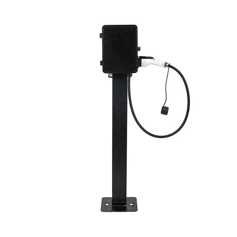
AC destination charging
AC Level 2 EV Charger
Regional AC variants
Workplace · Residential · Overnight fleets
Explore equipment ↗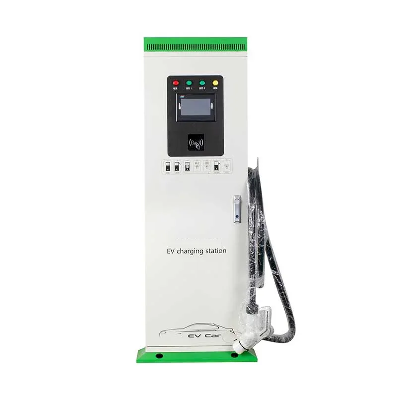
Compact DC fast charging
DC Fast Charger
30–80 kW
Retail · Dealerships · Fleet top-ups
Explore equipment ↗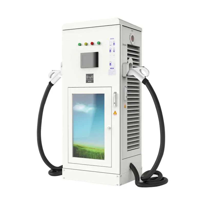
Higher-output DC charging
DC Fast Charger
120–180 kW
Busy commercial bays · Fleet hubs
Explore equipment ↗EXPLORE FURTHER