
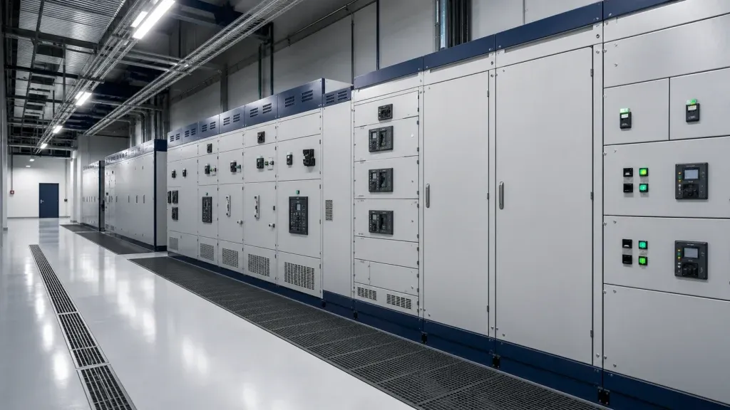
Switchgear is the one item on a solar or storage project where a vague enquiry produces a dangerous outcome. A board specified only by “incoming and outgoing ways” will be built to someone else’s assumptions, and the problems surface at commissioning – usually as a protection setting that will not discriminate, or a form of separation the maintenance team did not expect.
This guide covers what to pin down before you ask for a price.
Start from the single-line diagram
The single-line diagram is the specification. It carries the incoming supply, the protective devices, the outgoing circuits, the ratings of each, and the metering. Without it, any quotation is a guess with a number attached.
If you do not have a final diagram, send the load list and the supply characteristics. We will return a layout and a Bill of Materials for your approval before anything enters production.
Rated current is two numbers, not one
An assembly has a rated current for the busbar system and separate ratings for each outgoing circuit. A 6300 A busbar board can feed 63 A lighting circuits and 800 A feeder circuits from the same assembly – the outgoing ratings come from the load list.
The busbar rating must also be checked against the incoming device and against how the board will be loaded in practice. Boards that run hot age their insulation and their connections, and heat is the most common cause of premature switchgear failure.
Short-circuit rating: the kA and the duration
Every assembly carries a short-time withstand rating, expressed as a current for a duration – for example 65 kA for one second on LV, and typically 25 to 31.5 kA on MV. The number is set by the prospective fault current at the point of installation, which in turn is set by the supply transformer and the impedance upstream.
This is why the transformer and the switchboard should be engineered together. A transformer with lower impedance raises the fault level, and the board has to be rated for the result.
Form of separation: what you are actually buying
The “form” describes how the assembly is partitioned internally. It is the specification most often copied from a previous project without thought.
Reference table
Swipe horizontally to view all columns →
| Form | Separation | What it means in service |
|---|---|---|
| Form 2b | Busbars separated from functional units | Standard for distribution boards; work on a circuit means isolating the board |
| Form 3b | Busbars and terminals separated, functional units compartmented | An outgoing circuit can be worked on with the rest of the board live |
| Form 4a | Terminals in the same compartment as the functional unit | Higher continuity; cabling work still needs the unit isolated |
| Form 4b | Full separation including terminals | Maximum continuity; specified where downtime is unacceptable |
We build any of these, and we will tell you when the form you asked for is more than the application needs – the difference in cost and size is significant, and it is better spent on protection.
Protection and discrimination
A protection scheme is only correct if it discriminates: the device closest to the fault clears it, and the rest of the installation stays energised. Achieving that requires a coordination study against the actual fault levels, not devices picked from a catalogue.
On solar and storage projects this matters more than usual, because the site has multiple sources – grid, inverter and battery – and fault contribution flows from more than one direction.
IP and IK: match the enclosure to the room
IP30 is adequate inside a clean electrical room. Anything outdoors, in a plant room with wash-down, or in a dusty environment needs IP54 or better, and IK impact rating where the board can be struck.
Enclosure rating interacts with cooling. A sealed IP54 board in a hot climate needs ventilation or derating, and derating a board is cheaper to design in than to retrofit.
Type-tested or design-verified
IEC 61439 replaced the old type-tested assembly concept with design verification. The manufacturer must demonstrate compliance – by test, by calculation, or by comparison with a tested design – for strength, temperature rise, dielectric properties, short-circuit withstand and more.
Ask for the type-test or design-verification evidence specific to the assembly you are buying. A certificate for a different board from the same catalogue is not the same thing.
Component brands
ABB, Schneider and Siemens are our standard. Where you nominate brands, we build with them – and we flag the price and lead-time impact before you commit, because switchgear lead times are driven by component availability more than by assembly time.
What to send us
- Single-line diagram, or the load list plus supply characteristics
- Prospective fault level, or transformer rating and impedance upstream
- Form of separation required, and why
- Environment: indoor, outdoor, ambient temperature, dust or wash-down
- Preferred component brands, or “equivalent acceptable”
Confirm the minimum order and production scope for the selected assembly. Agree the drawing-approval process and manufacturing schedule before ordering; delivery timing depends on the approved design, component availability and destination.
Send the diagram and we will return a layout, a Bill of Materials and the applicable design-verification documents for the selected assembly and inspection requirements.
EXPLORE FURTHER
Related technical guides.
BUYER CHECKLIST
Buyer considerations for this scope
UL listing or IEC, and what does the authority accept?
US projects generally require UL or ETL listing, and the required listing should be stated on the enquiry rather than inferred. Equipment built to IEC practice without the US listing is a common cause of a failed inspection late in the programme.
Who produces the short-circuit and coordination study?
Usually the buyer engineer or the utility, and the panel has to be built to the ratings that study produces. Ordering switchgear before that study exists means either over-specifying everywhere or discovering an under-rated bus at inspection.
Which ratings have to be documented on the equipment?
Bus rating, short-circuit current rating, enclosure type such as NEMA 3R or 4X, breaker frames and ratings, wiring diagram, and the label set. These are what the inspector reads, so they should be specified as deliverables rather than assumed.
PRACTICAL ANSWERS
Questions buyers ask about this
What does the form of separation actually buy us?
It decides how much of the board stays live while part of it is worked on. Form 2b separates busbars from functional units. Form 4b also separates the terminals, so a circuit can be worked on with the rest of the board energised. Higher forms cost more and take more depth.
How is the short-circuit rating chosen?
From the prospective fault current at the point of connection, calculated in a fault study, and stated as a current over a duration such as 25 kA for 1 second. The rating has to cover the fault level with the transformer and any generation connected.
Withdrawable or fixed construction?
Withdrawable suits incomers and large feeders, because a unit can be swapped without de-energising the board. Fixed construction costs less and takes less depth, which suits small feeders that are rarely touched.
Which standard should we specify?
IEC 61439-1 and -2 for international projects. For North America, UL 891 dead-front switchboards or UL 1558 metal-enclosed switchgear. Where your arc-flash study requires it, internal arc testing to IEC 61641 is added.